Feb. 26, 2022
1. Interpretation of basic test parameters of UAV dynamic system
2. The basic parameters of the test experiment of UAV dynamic system
Wf-EDU-02 UAV dynamic test teaching instrument test kit
1. Understand the basic test parameters definition and test principle of UAV dynamic system;
2. Understand the sensor and position layout of dynamic test system measurement parameters;
3. Master the test measurement and data observation methods of dynamic test parameters;
The six basic test parameters of UAV dynamic system are thrust, torque, current, voltage, rpm and motor's temperature, which can be directly measured by the corresponding sensor on the dynamic test bench. Through understanding the basic parameters, the basic performance of UAV dynamic system can be mastered, which is convenient for the overall matching of the dynamic system.
Propeller thrust (G) Definition:
The lift is generated by the rotation of a propeller in the air. The principle of propeller pulling force needs to be explained through aerodynamics related to the concept and principle. The aerodynamics principle is relatively complex, we can simply understand the reaction force. The rotation of the propeller in the air makes the air under the blade speed up, resulting in downward airflow. We can understand it as that the propeller pushes the air, causing the air to move downward. Meanwhile, the air exerts an upward reaction force on the propeller, namely, the lift force (pull force).
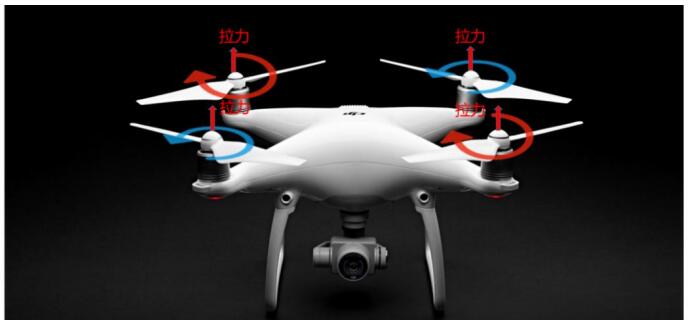
FIG. 1.1.1 Schematic diagram of propeller pulling force
Test propeller pulling principle of the test bench:
The tension generated by the propeller is transmitted to the test platform through the motor and acted on the tension sensor of the test platform. The tension sensor produces weak deformation and the strain gauge produces weak voltage change. Then the voltage signal is processed and calibrated to get the accurate tension value, which is displayed in real time by the test platform software.
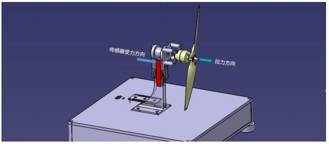
Figure 1.1.2 Force direction diagram of tension sensor
The definition of torque:
Torque is generated by the interaction between the propeller and the air when the propeller rotates in the air, which is opposite to the rotating direction of the propeller. It is called inverse torque, and the unit is N*m. Torque represents the air resistance caused by the rotation of the propeller, and the energy output by the motor to drive the rotation of the propeller is used to offset this torque, so the torque is both the air resistance caused by the propeller and the output torque of the motor (representing the load of the motor).
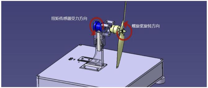
FIG. 1.2 Force direction intention of torque sensor
Torque principle of the test beach:
The counter torque generated by the propeller is transmitted to the test platform through the motor and acted on the torque sensor of the test platform. The torque sensor produces weak deformation and the strain gauge produces weak voltage change. Then the voltage signal is processed and calibrated to obtain accurate torque value, which is displayed in real time through the test platform software.
Definition of voltage and current:
Voltage (V) current (A) refers to the input voltage and current of the UAV dynamic system, that is, the voltage and current input by the power battery to the electrical modulation. The total power of the dynamic system can be obtained from the voltage and current, which represents the energy consumption of the power system.
Voltage in UAV generally refers to the battery voltage, and the number of batteries in a dynamic system is generally fixed, voltage will decrease with the increase of power consumption, but also due to battery aging or output current is too large and rapidly reduced. The current is changed with the change of load, and the current that a dynamic system can withstand is limited, when the current is too large, the dynamic system (including the battery, electric conditioning, motor) will heat seriously, if the continuous work for a long time, it will face the risk of burning.
The test voltage and current principle of the test bench:
Voltage and current are respectively through the voltage sensor and current sensor for data acquisition. Voltage and current sensors are integrated in the test table on the power supply main-board. The power supply's main-board has power input and output and the main-board of power supply is connected to the power input, the output is connected to the electric adjustment. The voltage and current test is carried out in real time during the operation of the power system.
RPM definition:
RPM refers to the speed of propeller rotation driven by motor, in unit of r/min, which can also be expressed as ![]() . It is one of the necessary parameters to calculate the motor output power (shaft power), and represents the propeller and motor working conditions. The control principle of UAV is realized by controlling the speed of propeller driven by motor. Test speed principle of the test bench: WF-EDU-02 test platform adopts the measurement method of commutation speed, and detects the speed of motor and propeller by collecting the commutation frequency of electric adjustment. It only needs to take any two of the three output lines of electric adjustment as the input signal of the acquisition motherboard, then the value of motor speed can be read in real time.
. It is one of the necessary parameters to calculate the motor output power (shaft power), and represents the propeller and motor working conditions. The control principle of UAV is realized by controlling the speed of propeller driven by motor. Test speed principle of the test bench: WF-EDU-02 test platform adopts the measurement method of commutation speed, and detects the speed of motor and propeller by collecting the commutation frequency of electric adjustment. It only needs to take any two of the three output lines of electric adjustment as the input signal of the acquisition motherboard, then the value of motor speed can be read in real time.
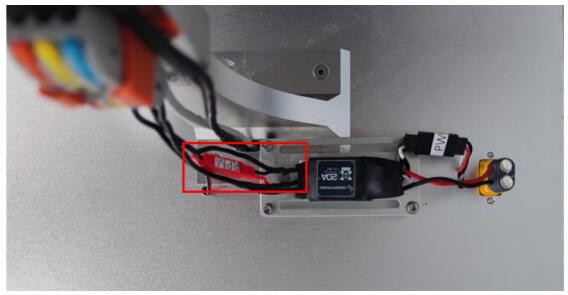
Figure 1.4 Schematic diagram of electric speed regulating signal line
Temperature definition:
Temperature (℃) refers to the heating temperature of the motor under the working state. The heating of the motor is mainly generated by the coil winding of the stator part (current-heat effect). The increase of motor temperature will affect the working state of the motor. First, the permanent magnet attached to the motor shell, with the increase of temperature, the magnetic conversion efficiency of the permanent magnet decreases, directly affecting the efficiency of the motor, if the temperature rises further, the permanent magnet will have the risk of demagnetization. On the other hand, the shell temperature indirectly reflect the temperature of the motor coil inside, generally the brush-less motor coil made by high-temperature enameled wire winding and become, generally 200 degrees of heat-resistant, if the shell temperature of 100 degrees Celsius, explain the internal coil temperature is very high, and the internal heating coil, motor cooling capacity is insufficient, that can make the temperature rising sharply, which risking of burning the motor.
Test motor temperature principle of the bench:
The heating reference of the motor can be obtained by monitoring the temperature of the stator coil, shaft or shell of the motor, in which the coil temperature can directly reflect the heat of the motor, and the shaft temperature is closer to the coil temperature than the shell temperature (the shell is the rotor part of the motor, and there is a gap between the stator). WF-EDU-02 test bench uses infrared temperature measurement method to test the shaft temperature of the motor.
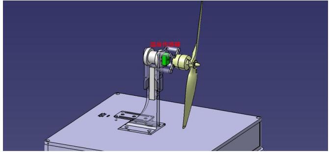
Figure 1.5 Schematic diagram of temperature sensor
E-mail: sandy@wing-flying.com
Add.: 7th Floor, B2#,Animation Building, Sino-Singapore Tianjin Eco-City