Jan. 12, 2022
Experimental equipment and tools:
WF-EDU-02 test bench: test bench main body, isolation cage, power line, data line;
Power system: 20A electric adjustment, 3S battery (can be replaced by the internal power supply of the test bench), a set of test motor and propeller: motor model 2312-KV1000, propeller model 9450, a detachable motor.
Other assembly tools: hexagon socket, bolt, propeller assembly clamp.
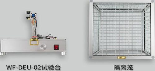
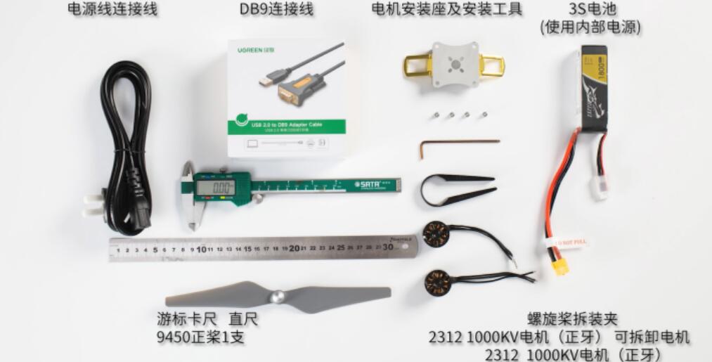
Figure 2.1 Experimental equipment and tools
Document preparation: Test motor parameter table (Appendix 1);
Electrical Adjustment Parameter Table (Appendix 2)
2.1 Measurement of basic parameters of propeller and motor
(1) Propeller diameter measurement:
The propeller is placed on the ruler, and the propeller and ruler are kept level. One end of the propeller tip is aligned with the zero scale of the ruler, and the diameter (mm) of the propeller is read at the other end of the propeller tip. The diameter value read is divided by 25.4(1inch=25.4mm), which is the diameter parameter value of the propeller (inch). By comparing the measured parameters with the marked parameters of the propeller, the meaning expressed by the parameters can be clarified.

Fig.2.2.1 Schematic diagram of propeller measurement
Note: the above measurement method of propeller diameter can only be used for rough measurement, not precise measurement.
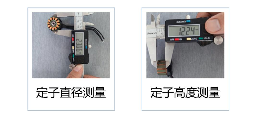
Figure 2.2.2 Stator diameter (23mm) and Height (12mm) of 2312 motor
2.2 Motor KV value test experiment
(1) Refer to the operation experiment steps of course 1 to complete the installation of motor and test bench, test bench electricity, software connection and electric adjustment stroke calibration.
(2) Software setting: Enter the system setting interface and set the polar logarithm of the motor according to the basic parameters of the motor (Attachment 1). (The test bench measures the speed by testing the commutation signal of electric adjustment. It is necessary to set the correct pole logarithm of the motor to make the measured speed correct)
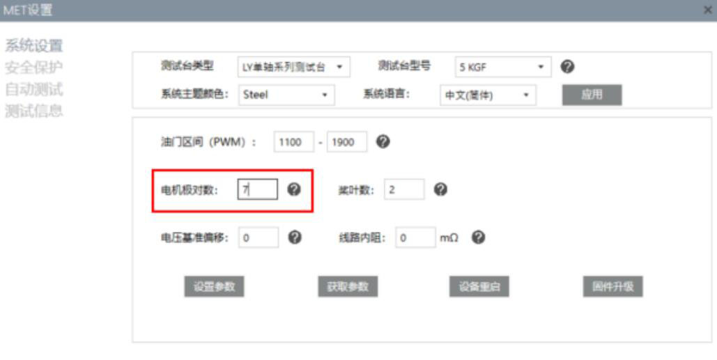
FIG. 2.2.3 Polar logarithm setting of motor
(3) Voltage adjustment: open the motor switching power supply, rotate the motor voltage adjustment knob, observe the software voltage indication, adjust the test bench voltage to 10V (±0.01V).

Figure 2.2.4 Schematic diagram of motor voltage adjustment
(4) Motor KV value test: unlock the throttle, drag the throttle position to 100%, at this time the power supply will produce a little pressure drop, voltage value is less than 10V. Keep 100% throttle state, continue to adjust the motor voltage adjustment knob to adjust the test bench voltage to 10V (±0.01V). Record motor commutation speed value. At this time, the motor speed divided by 10 (KV value = speed/voltage), is the actual KV value of the motor. (Due to the production quality control of the motor and different production batches, the actual KV value of the motor will be different from that of the original model, generally within 10%).

FIG. 2.2.5 Test diagram of motor KV value
(5) Motor KV value verification test: After recording the motor speed in step (4), continue to adjust the voltage to 9V (±0.01V) or 11V (±0.01V) and record the motor speed again. The difference between the recorded motor speed and step (4) is also the actual KV value of the motor.((4) and (5) There is a little error in KV values of the two tests, which is a normal phenomenon).
2.3 Dynamic system current safety test
The current safety test of power system is mainly based on the explanation part of experimental principle, and the current safety operation principle in the basic parameter matching principle of motor, electric modulation and battery, that is, after the motor is matched with the propeller, the dynamic system operation test is carried out to ensure that the tested current value should be less than the maximum current of the motor in 100% throttle state.
(1) Open the safety protection interface, set the protection mode to warning and close the throttle, click Enable protection, set the threshold of current protection to 15A, and set the temperature protection to 60 degrees Celsius (the current is set to 15 because the maximum continuous current of the motor is 15A, and 60 degrees is also the safety setting for the overload of the motor).
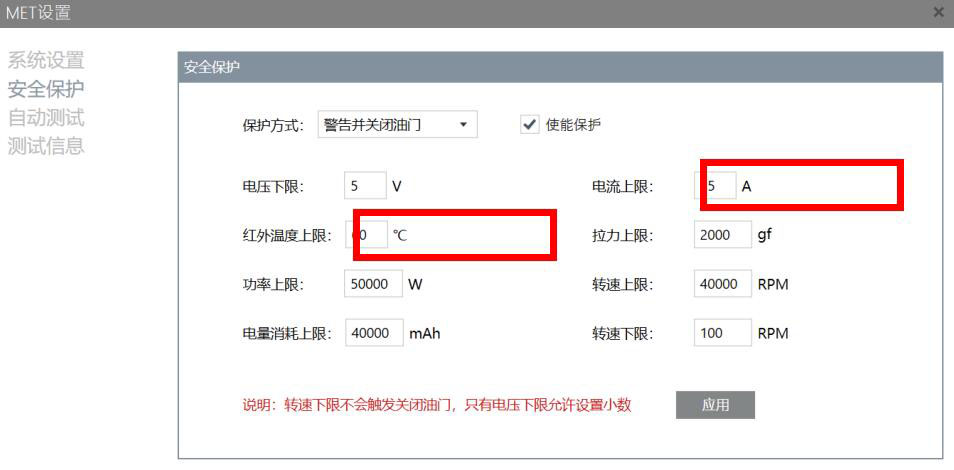
Figure 2.3.1 Security Protection setting window
(2) Complete motor and propeller positive and negative rotation test and installation according to experiment Course 1.
(3) Before the test, please place the isolation cage on the test table:
1)Fasten the lock, and turn on the motor power switch.
2)Adjust the test voltage to 11.4V, click the current to clear.
3)Click the throttle to unlock.
Gradually drag the throttle position from 0 to 100% to observe the current change.
Under 100% throttle, if the current is less than 15A, the current is in line with the principle of safe operation.
1) Click the throttle to lock and complete the test.
2) Adjust the voltage to 15.2V (±0.1V).
3) Click the throttle to unlock.
4) Click current zero.
Gradually drag the throttle position from 0 to 100% to observe the current change. Under 100% throttle, the current exceeds 15A, the test bench is automatically locked, and the dynamic system matching does not meet the current safety operation principle.
This course is divided into two parts: the first part is the explanation of experimental principle, which explains the basic parameters of each component of UAV dynamic system in detail. The second part is the experiment and training part, which mainly includes three experimental modules: measuring the basic parameters of the motor and propeller, testing the KV value of the motor and testing the safety of the dynamic system current.
Note: After the experiment, please restore the experiment equipment to the state before the experiment, and put the experiment equipment and tools back to the designated position.
E-mail: sandy@wing-flying.com
Add.: 7th Floor, B2#,Animation Building, Sino-Singapore Tianjin Eco-City