Jun. 11, 2022
The development of miniature, cold- gas thrusters for on-orbit propulsion of such small devices as remotely piloted cameras and for inclusion in astronaut propulsion backpacks gave rise to a need to measure thrusts ranging from 0.04 to 0.8 lb (0.2 to 3.6 N). In addition, there was a need to measure thrust in a vacuum environment as well as in air at a pressure of 1 atmosphere (0.1 MPa), and over a wide range of propellant inlet pressures. The primary obstacle to be overcome for such measurements was to solve the problem of delivering the cold-gas propellant (compressed nitrogen gas) to the thruster without affecting thrust measurements, particularly those below 1/4 lb (1 N).
Methods for measuring larger thrusts include the use of flexible tubes or rotating fluid couplings to deliver propellants. However, in the present low-thrust application, the forces applied by flexible tubes to thrust sensors would be large with respect to the thrust being measured. In addition, the forces generated by flexible tubes vary with changes in propellant pressures and apply off-axis loads to the thrust sensors. The internal frictional forces in rotating fluid couplings, and the variations of these forces with pressure, would also be too great with respect to the low thrusts to be measured.

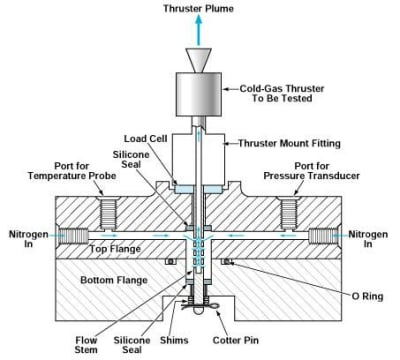
This Thrust Stand has been calibrated to yield accurate measurements of thrusts from 0.02 to 0.61 lb (0.09 to 2.7 N). This view is a simplified cross section; some details are omitted.
The figure is a cross section of a thrust stand designed for measuring small thrusts in vacuum or in air at atmospheric pressure. A readily available doughnut-configuration load cell is used as the thrust sensor. The doughnut configuration was chosen because its central hole makes it possible to make the propellant-flow path coaxial with both the thruster and the load cell. The load cell is equipped with a vent port so that the pressure of air in its internal cavity always equalizes with the pressure of the surrounding air, to prevent undue pressure-related shifts in load-cell output.
A flange assembly and flow stem are included to provide for delivery of propellant coaxially through the load cell to the thruster. The flow stem is also part of a thruster-mount fitting, which transfers thrust from the thruster to the load cell. The coaxial arrangement of the thruster, load cell, and flow stem eliminates all off-axis loads.
The flow stem was designed to protrude through both the top and bottom flanges so that propellant pressure is axially balanced on the stem in opposing directions. This was done to negate the force on the load cell produced by the static pressure and by variation of the static pressure of the propellant. In practice, this design feature proved successful, balancing 98.7 percent of the force [7.8 out of 7.9 lb (34.7 out of 35.1 N)] at a propellant pressure of 258 psi (1.78 MPa).

One focus of design efforts was the problem of how to best seal the gap between the flow stem and the flanges to prevent the escape of nitrogen, while allowing for consistent reactions from the load cell for a given thrust. Initially, the flange passageways incorporated internal O-ring grooves, with the O-ring sealing against the flow stem in the top and bottom flange. Since full deflection of the load cell was to provide an alternate method of sealing between the flow stem and flanges to eliminate shifting of the seals, O rings were replaced with a silicone sealant. It was reasoned that once the sealant became cured, the adhesion of the sealant to the flow stem and flanges would ensure a fixed geometry, without the slippage between dissimilar surfaces that had occurred in the use of the O rings. Like the O rings, the new silicone seals would flex microscopically, but they would not slip along the flow stem or shift in their grooves as the O rings did. A pourable silicone sealant with proper viscosity in the uncured state and proper shear strength in the cured state was selected. An assembly method and tools were devised to support pouring and curing of the silicone seals during assembly of the thrust stand. During testing of the silicone seals, no leakage was observed at pressures up to 270 psi (1.86 MPa).

● A shoulder on the thruster mount fitting holds preload weights that are needed to optimize the sensitivity of the load cell.
● A raised wall on the top flange protects the load cell, which is delicate.
● Leakage relief paths from the silicone seals prevent unwanted pressurization in the event of a leak.
● Ports for temperature and pressure sensors are included.
● A cotter pin and shims retain the flow stem in the flange assembly. Shim stack height is set as needed to carry any inadvertent loads applied to the bottom of the flow stem during handling and installation, thus protecting the silicone seals from damage.
Calibration of the thrust stand began with pressurizing it to one of the pressures desired for testing thrusters. Next, calibrated brass weights were placed on the thruster nozzle, and the electrical output of the load cell was recorded. After calibrations were completed, the thruster was fired several times, then calibration was repeated.
During a test program, the thrust stand was calibrated in thrust ranges of 0.02 to 0.16 lb (0.09 to 0.71 N) and 0.39 to 0.61 lb (1.7 to 2.7 N). The error in the measurements was ±5 percent of indication in the low range and ±3 percent of indication in the higher range. This combination of ranges and accuracies amounts to an exceptionally wide useful overall range for a thrust-measurement system. The thrust measurements obtained in thruster firings were found to be equally or more repeatable (that is, characterized by error bands of equal or smaller width), in comparison with the thrust measurements obtained during calibration.
Mounting the load cell under the bottom flange in a holding fixture would make it possible to replace the load cell easily with a load cell of a different measurement range. Thrust would still be transferred to the load cell coaxially, but it would be transferred from the bottom tip of the flow stem, through a thermal-isolation fitting, to the load cell. Not only would the replacement of the load cell be much simpler; in addition, this configuration would thermally isolate the load cell from the thruster and propellant, thus providing for temperature conditioning of the thruster and propellant beyond the range allowable for the load cell. This configuration would also make it possible to use a larger diameter flow stem to accommodate thrusters with higher flow rates.
In this application, time constraints dictated the purchase of a best available, off-the-shelf load cell that had a normal measurement range of up to 2 lb (8.9 N). The use of the load cell for a wide range of measurements is what made it necessary to perform both a low-range calibration and a separate high-range calibration to ensure accuracy. Time permitting, future versions of the thrust stand would incorporate lower-range load cells for the lowest of thrust measurements.
E-mail: sandy@wing-flying.com
Add.: 7th Floor, B2#,Animation Building, Sino-Singapore Tianjin Eco-City