Aug. 13, 2025
The ESC serves as the intermediary between the battery and the motor, regulating motor rotation by sending timed electrical signals that adjust speed. It converts the battery’s direct current into a three-phase alternating current using a switching system, which then drives the motor.
The flight controller controls motor speed, whether in a drone, RC car, or electric plane. Increasing throttle raises output power, which changes the switching rate within the ESC circuitry.
ESCs receive throttle signals from the remote controller using various protocols, including PWM, Oneshot, Multishot, and Dshot. These protocols mainly differ in signal frequency; higher frequencies allow faster signal updates and quicker responses. Dshot stands out as it uses digital signals rather than analog, offering improved reliability, higher resolution, and reduced sensitivity to electrical noise.
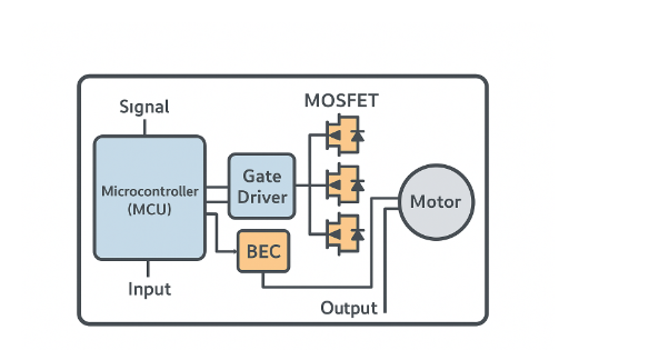
An ESC contains several key components that enable precise motor control, including the microcontroller (MCU), gate driver, MOSFETs, and in some cases, a battery eliminator circuit or device manager adapter.
The microcontroller is central to ESC operation, performing three main functions:
Running firmware that interprets signals from the flight controller and maintains a control loop.
Tracking the motor’s position to ensure smooth acceleration.
Sending pulses to the gate driver to execute the desired commands.
ESC firmware is typically pre-installed by the manufacturer, though open-source alternatives are available. Common hobby drone firmware includes variations of BLHeli (BLHeli_S or BLHeli_32), SimonK, and KISS. Firmware must be compatible with the ESC hardware, as it impacts performance and protocol support.
The microcontroller also determines rotor position through sensored or sensorless systems. Sensored systems use electronic sensors for precise position tracking, suitable for low-speed, high-torque applications like ground vehicles. Sensorless systems rely on back EMF to estimate rotor position, which works well at high speeds, making it ideal for propeller-driven applications. Sensorless ESCs are generally more efficient, cost-effective, and reliable for high-speed use.

The gate driver serves as the intermediary between the microcontroller and the MOSFET gates. When it receives a low-voltage signal from the microcontroller, the gate driver amplifies it into a higher-voltage signal suitable for the MOSFETs. Compared to the microcontroller, the driver offers lower resistance and can supply higher current, which increases signal switching speed. This results in faster MOSFET switching and reduced heat generation. In some ESC designs, optical isolation chips are used to separate the low-voltage microcontroller from the high-voltage transistors; ESCs with this feature are often referred to as Opto-ESCs.
Many ESCs include a built-in Battery Eliminator Circuit (BEC). Despite its name, the BEC does not replace the main battery; instead, it functions as a voltage regulator, removing the need for a separate battery to power onboard electronics. The BEC steps down the voltage from the main battery—typically to 5 V—providing a safe and stable power supply for the throttle receiver and other onboard devices.

Pulse Width Modulation (PWM) was the first ESC control protocol and remains widely used today. PWM regulates motor speed using timed power pulses based on input from the flight controller. The throttle controller sends a signal to the ESC’s microcontroller, instructing it how much voltage to draw from the battery and deliver to the motor.
The signal is transmitted as a series of voltage pulses, where the duration of the “on” time determines how long voltage is applied. Between these pulses are “off” periods with no voltage. The longer the “on” time relative to the “off” time, the more power is delivered and the faster the motor spins. This ratio of “on” to “off” time is called the duty cycle.
In PWM systems, pulse lengths typically range from ~1000 μs to ~2000 μs. Originally, pulses were sent every 50 ms, but modern systems now transmit signals every 2.04 ms (490 Hz). At a frequency of 500 Hz, the signal could potentially be continuously “on,” which the ESC may interpret as a fault.
The gate driver receives the voltage signal from the microcontroller and applies it to the MOSFETs, controlling their switching across the three motor phases. The higher the voltage delivered to the MOSFETs, the faster they switch phases, resulting in a higher rotor speed.
Control frequency refers to how often the flight controller sends throttle commands to the ESC. In PWM-based systems, this corresponds to the rate at which voltage pulses reach the ESC’s microcontroller. Depending on the protocol, this can range from 50 Hz in older systems to 490 Hz or higher in modern analog setups. A higher control frequency allows the ESC to receive more frequent updates, improving throttle responsiveness and reducing system latency.
Switching frequency describes how often the ESC’s MOSFETs turn on and off to generate the three-phase AC signal that drives the motor. This internal switching occurs much faster than the control frequency—typically between 8 kHz and 50 kHz—and is managed by the ESC’s microcontroller and gate drivers. Higher switching frequencies create a smoother current waveform, reducing motor noise and enhancing efficiency at low throttle. However, at higher throttle, frequent switching can produce additional heat in the MOSFETs, slightly lowering efficiency.
In simpler terms, the flight controller instructs the ESC at the control frequency, and the ESC drives the MOSFETs at the faster switching frequency to execute those instructions.
An ESC protocol is essentially the communication “language” used by flight controllers to interact with the ESC. Each protocol transmits unique signal patterns to convey throttle information, and by adjusting the signal timing, it controls the motor’s rotation speed.
Before 2015, PWM was the only ESC protocol widely used in small UAVs. Since then, several new protocols have emerged, and most hardware developed after 2017 supports all or most of them.
The most common protocols include Oneshot125, Oneshot42, Multishot, and DShot300, DShot600, and DShot1200. Oneshot and Multishot use analog signals similar to PWM, while DShot (Digital Shot) uses a digital signal.
Analog protocols require calibration to synchronize the oscillators (clocks) of the flight controller and ESC. Without proper calibration, the ESC may misinterpret signal lengths, causing delayed or incorrect motor responses. Digital protocols like DShot eliminate this need, providing more reliable and consistent communication.
DShot1200 is currently the fastest protocol, transmitting 1,200,000 bits per second. Its fixed signal length is just 13 μs—almost twice as fast as Multishot’s 25 μs signal length. While DShot1200 is extremely fast, in practical use the performance difference between DShot600 and DShot1200 is often minimal.
A major advancement in the DShot protocol is bi-directional communication, which allows the ESC not only to receive commands from the flight controller but also to send data back. This enables telemetry such as motor RPM to be transmitted using the same signal wire, reducing the need for additional sensors and wiring.
Bi-directional DShot can improve drone performance in several ways:
Enhanced RPM filtering: The controller receives real-time motor RPM data, allowing it to refine notch filters on gyro data (pitch, yaw, roll).
Reduced signal delay: With fewer frequencies to filter, processing time decreases, resulting in faster signal transmission and more responsive motor control.
Improved motor performance: Less filtering reduces resistance in the system, enabling smoother, cooler operation. Noise reduction also minimizes vibration, enhancing overall stability and flight performance.
The Controller Area Network (CAN) bus was originally developed to enable multiplexing in automobiles, reducing wiring complexity and cost. It ensures that each device on the network receives only the messages intended for it, while using arbitration to prioritize critical communications.
Drones, like cars, require reliable and efficient communication between components such as flight controllers, ESCs, GPS modules, and sensors. CAN is well-suited for these applications due to its robustness, support for real-time data exchange, and resistance to electrical noise. However, CAN only defines the transport layer—it does not dictate how devices interpret the transmitted data. This is where higher-level protocols come into play.
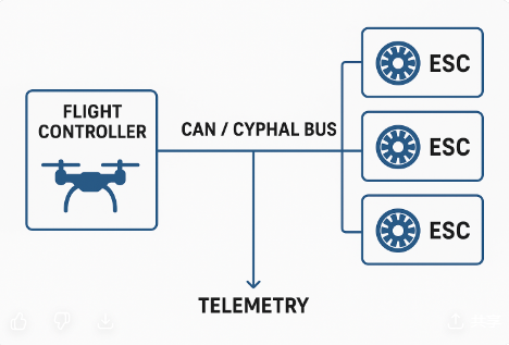
Cyphal is a protocol specifically designed for high-integrity distributed systems like UAVs and robotics. Running over Ethernet, CAN, or CAN FD (Flexible Data-rate), Cyphal defines the structure and meaning of messages exchanged between devices. It supports low-latency communication, facilitates interoperability among components from different manufacturers, and allows telemetry to be transmitted alongside control commands.
Unlike legacy protocols such as PWM and DShot, which require a dedicated signal wire for each ESC, Cyphal enables multiple ESCs to communicate over a shared two-wire network. This allows simultaneous transmission of throttle commands and collection of additional telemetry data, including voltage, current, temperature, and more.
The ESC’s main function is to regulate power from the battery to the brushless motor. For example, if you set the throttle to 50%, the ESC will deliver roughly 50% of the motor’s available power. How this “power” is defined depends on the ESC firmware—some measure it by average voltage, others by target speed, and some use a combination of both.
On the battery side, the ESC has two wires: a red positive wire and a black negative wire. On the motor side, there are three wires that connect directly to the brushless motor. If the motor spins in the wrong direction after connection, simply swapping any two of the three wires will reverse its rotation. Additionally, the ESC provides a connection to the throttle receiver, which is powered through the BEC.
A brushless motor consists of two main components: the rotor, which contains permanent magnets, and the stator, which houses copper coils. When current flows through a stator coil, it becomes an electromagnet with a North and South pole. If the electromagnet’s polarity aligns with the facing permanent magnet, like poles repel, causing the rotor to spin. The ESC delivers current as a three-phase signal, continuously changing the polarity of the stator electromagnets to keep the rotor turning.
To start this process, the ESC must know the rotor’s position to determine which coils to energize. In sensored motors, Hall Effect sensors provide this information, allowing the ESC to precisely synchronize the phase output with the rotor angle, ensuring smooth acceleration. In sensorless motors, which are more common in UAVs, the startup is slightly less precise. The ESC sends a predetermined sequence to initiate rotation, and once the rotor reaches sufficient speed, the back electromotive force (back EMF) enables the ESC to estimate the rotor position accurately and synchronize the pulses.
The ESC’s current rating should typically be 10–20% higher than the motor’s maximum current. This margin helps prevent overheating and ensures reliable operation at full throttle. Going significantly higher than this range adds unnecessary weight.
Every ESC has a maximum voltage limit, often specified either as a voltage range or as compatible battery cell counts. Many ESCs allow you to configure a Low Voltage Cutoff (LVC), which triggers an alert or reduces power output when the battery voltage drops too low, protecting the battery from damage.
Effective thermal management is essential for reliable ESC performance. Poor airflow or high environmental temperatures can raise internal operating temperatures, reducing the ESC’s effective current rating and shortening its lifespan. Dedicated heatsinks, optimized PCB layouts, or forced-air cooling can help ensure efficient heat dissipation.
Motor noise often originates from the ESC’s operation. ESCs with low switching frequencies can produce sharp square waves that cause motor coils to vibrate, creating noticeable noise—sometimes louder than the propeller.
When wiring a quadcopter, you can use an individual ESC for each motor or a single 4-in-1 ESC board with four motor connectors. Using four separate ESCs can help distribute heat for high-power motors, while a 4-in-1 ESC saves space and reduces hardware weight.
We’ve covered the basics of ESCs: how they work, their key components, the communication protocols, and how they integrate with CAN bus systems, brushless motors, and drones. Understanding this essential component will help you improve both your knowledge and your drone builds.
At WingFlying, we provide high-quality ESCs and drone components designed for performance, reliability, and innovation. Whether you’re building a DIY drone or upgrading your fleet, WingFlying has the right solutions to take your aerial projects to the next level.
E-mail: sandy@wing-flying.com
Add.: 7th Floor, B2#,Animation Building, Sino-Singapore Tianjin Eco-City